To the top

Australia International

Product Tabs

Product Details
HurricaneTie
HurricaneTie
H1.81Z
H1.81Z
H1.81Z Illustration
H1.81Z Illustration
H2.5A / H2.5ASS
H2.5A / H2.5ASS
H2.5A / H2.5ASS Illustration
H3Z
H3Z
H3Z Illustration
H3Z Illustration
S/H1A
S/H1A
S/H1A Illustration
S/H1A Illustration
S/H2.5
S/H2.5
S/H2.5 Illustration
S/H2.5 Illustration

Hurricane Ties provide a positive connection between the truss/rafter and the wall of the structure to resist wind and seismic forces. These ties connect both solid-sawn and engineered timber across a wide range of applications. Some hurricane tie models are available with additional corrosion resistance for exterior and treated-timber applications.

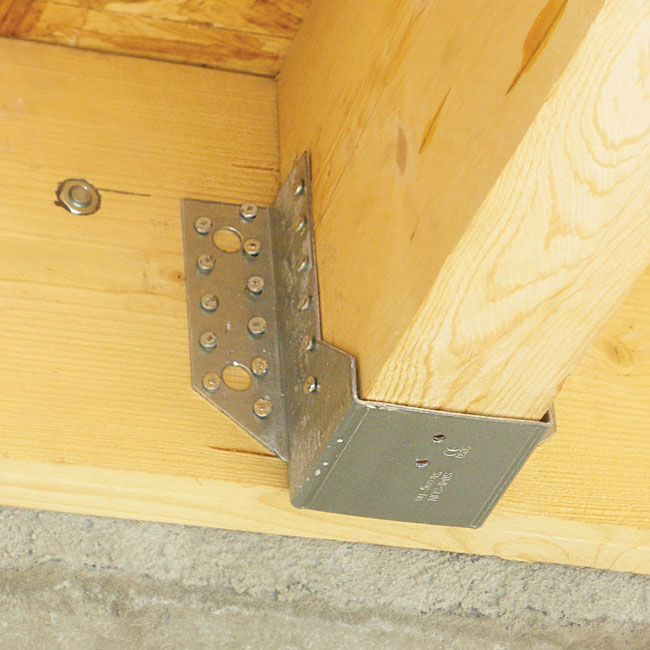
The H1.81Z Hurricane Tie is designed for use with 45mm structural timber framing to provide a stronger connection between the top plate of the wall and rafter. It's ideal for connections when there are higher-load demands on the structure, like a heavy snow load, and provides lateral resistance in a seismic event. It also suits for bearer to joist connection in flooring and deck framing applications.

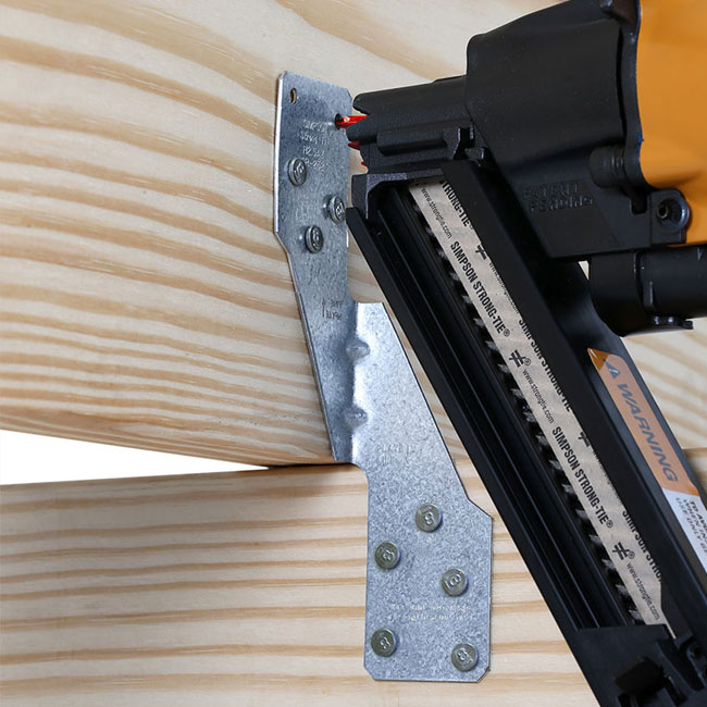
The H1.81Z installs with half the nails that are needed for two single-sided twist straps (like the H2.5A) and offers a higher lateral allowable load, making it a cost effective and higher-performing solution to tie down a rafter roof.

The H2.5A connects the truss/rafter to the top plate and is also suitable for joist to bearer connections. It is available in galvanised and stainless steel for extra corrosion protection.

Please check Corrosion Information if it is suitable for your application.

Material
  • Carbon Steel 1.3mm thick
Finish
  • ZMAX® Galvanised: H1.81Z, H2.5AZ, H3Z
  • Z275 Galvanised: H2.5A
  • 316 Stainless Steel: H2.5ASS
Features & Benefits
  • Resists high winds and seismic forces
  • Provides a secure hold to help weather storms
  • H1.81 has a wider seat to fit 45 mm structural timber framing
  • Engineered swages for extra strength and to minimise deflections
  • Install in pairs on either side of the rafter/truss/joist to provide resistance to uplift and lateral forces
  • May be used for general tie purposes, strongback attachments, and as all-purpose ties where one member crosses another
  • H2.5A is available in 316 Stainless Steel for extra corrosion protection
  • Install with Simpson Strong-Tie 8d common nails or Strong-Drive SD screws
Installation
  • Use all specified fasteners 
  • Simpson Strong-Tie Stainless Steel connectors require stainless steel fasteners
  • Ties can be installed with flanges facing inward or outward
  • Hurricane ties do not replace solid blocking
Applications
  • Rafter/Truss/Joist tie down
  • Top Plate-to-Stud tie down
  • Decking Joist tie down
  • Structural timber framing
Model No. Table

Model No.

Fasteners
(No. — Length x Dia., mm)

Design Capacity (kN)

AU

Design Capacity (kN)

NZ

Rafter/Joist

Top Plates/Bearer

Stud

Uplift
k1 = 1.14

F1
k1 = 1.14

F2
k1 = 1.14

Uplift
k1 = 1.0

F1
k1 = 1.0

F2
k1 = 1.0

H1.81Z

6 – 38 x 3.75

4 – 38 x 3.75

2.25

2.23

1.29

1.86

1.84

1.07

H2.5A
H2.5AZ

5 – 38 x 3.32

5 – 38 x 3.32

2.35

0.49

0.48

2.32

0.49

0.48

H2.5ASS

5 – 38 x 3.32

5 – 38 x 3.32

1.88

0.34

0.34

1.85

0.34

0.34

H3Z

4 – 38 x 3.32

4 – 38 x 3.32

1.98

0.31

0.76

1.86

0.29

0.76

  1. Design Capacity is the lesser of (1) the Characteristic Capacity multiplied by the Australian Capacity Factor, or the NZ Strength Reduction Factor (φ), and applicable the k modification factors following AS 1720.1 and NZS 3603 and (2) the Serviceability Capacity which is the load at 3.2mm joint slip. Design Capacity is the minimum of test data and structural joint calculation.
  2. For Australia, the Capacity Factor (φ) is 0.85 for nails and screws for structural joints in a Category 1 application. Reduce tabulated values where other Category applications govern. For New Zealand, The Capacity Factor (φ) is 0.8 for nails.
  3. Duration of Load Factor (k1) is as shown. Reduce Duration of Load Factor (k1) where applicable. Capacities may not be increased.
  4. Timber species for joint design is seasoned Radiata Pine, which is Australia Joint Group JD4 per AS 1720.1 Table H2.4.
  5. Allowable loads in the F1 direction are not intended to replace diaphragm boundary members or cross-grain bending of the truss or rafter members
  6. When cross-grain tension cannot be avoided in the members, mechanical reinforcement to resist such forces may be considered
  7. H1.81Z shown on the outside of wall assumes a min. overhang of 90mm. Installation on the inside of wall is acceptable with detailing for the uplift continuous load path by Designer.
  8. For parts installed on the outside of wall where only three plate fasteners can be accessed, reduce table loads by 0.75 for single part and 0.875 for two-part installations.

S/H1A Technical Data - Steel Frame 

Model No.

Fasteners

Truss Thickness mil (ga.)

Allowable Uplift Load (lb.)

Plate/Wall Stud Thickness mil (ga.)

Truss

Top Track

Stud

33 mil (20 ga.)

43 mil (18 ga.)

54 mil (16 ga.)

S/H1A

(4) #10

(3) #10

(1) #10

27 (22)

470

470

470

(4) #10

(3) #10

(1) #10

33 (20)

510

550

690

(4) #10

(3) #10

(1) #10

43 (18)

510

550

690

(4) #10

(3) #10

(1) #10

54 (16)

520

675

850


  1. Tabulated loads based on truss members with yield strength, Fy, of 50 ksi and tensile strength, Fu, of 65 ksi. Reduce tabulated load proportionally for lower truss member steel strength. For example: 43 mil (18 ga.) truss member with a yield strength, Fy, of 33 ksi and a tensile strength, Fu, of 45 ksi is connected to 43 mil top track and wall stud. The adjusted allowable load is then 550 lb. x minimum [33/ 50 or 45/ 65] = 363 lb.
  2. See Fastening Systems for more information on Simpson Strong-Tie fasteners.


S/H2.5 Technical Data - Steel Frame 

Model No.

Connector Material Thickness mil (ga.)

Fasteners

Allowable Uplift Load (lb.)

33 mil (20 ga.)

Truss / Rafter

Top Track

Stud

Uplift

Lateral

F1

F2

S/H2.5

43 (18)

(4) #10

(4) #10

390

90

125


  1. Loads are based on attachment of cold-formed steel members having a minimum thickness of 33 mil (20 ga.).
  2. Hurricane ties are shown installed on the outside of wall for clarity. Installation inside of wall is acceptable. For Continuous Load Path, connections in the same area must be on same side of wall.
  3. See Fastening Systems for more information on Simpson Strong-Tie fasteners.


Brochures & Catalogues

Brochures and Catalogues

PDF icon Flyer - Hurricane Tie
Installation Guides
Technical Data & Docs
CAD Library
Alternative Products

Alternative Products

E5_Reinforced Angle Bracket

E5 Reinforced Angle Bracket is suitable for structural applications in framing and timber-frame houses for general connecting of timber at 90° angles. Typical applications include fixing trusses, studs, purlins, beams and posts.

A35

The versatile A35 Reinforced Angle Brackets provide a way to make a straight angle of 90° connection. The A35 Angle Bracket’s exclusive bending slot allows instant, accurate field bends for two and three-way ties.

Inspiration
Request a Demo

Request a Demo/Sample*

Experience the innovation of Simpson Strong-Tie products and how we can help you build safer, stronger structures. Please fill out your details and submit the form below. We’ll be in touch to provide you a demo and/or send you samples*.

Request a Demo/Sample*

Experience the innovation of Simpson Strong-Tie products and how we can help you build safer, stronger structures. Please fill out your details and submit the form below. We’ll be in touch to provide you a demo and/or send you samples*.

Structural Connections


Unmatched Quality from the Truss to the Foundation

With nearly 60 years of field and R&D experience, Simpson Strong-Tie® timber connectors are manufactured to the industry's highest standards. From framing angles to straps to heavy-duty joist hangers, we offer the most diverse product line so that you have the right product for the job.

Simpson Strong-Tie® connectors offer unmatched quality with laboratory and field testing, and are backed by our uncompromising commitment to customer service. As the company that built the connector industry, you can count on Simpson Strong-Tie® to work closely with builders, engineers and building officials to deliver innovative, building code-compliant solutions to help build safer, stronger structures economically. Download the Structural Connectors Overview Flyer.

Timber Connectors

From testing to service to availability, everything we do is engineered to ensure your project's success. With every product, you know you are getting the quality, value, service and on-time delivery that we have built our reputation on for the past 60 years.

From straps and ties to joist hangers and much more, Simpson Strong-Tie® structural connectors increase the strength and safety of timber-frame structures. Each connector is unique to Simpson Strong-Tie and is designed for specific applications without the need to adapt metal plating to suit a connection. 

Steel Frame Connectors

From fully tested and engineered connectors and clips Simpson Strong-Tie® provides comprehensive structural solutions for cold-formed steel construction. From steel-to-steel connections to full-scale lateral solutions and curtain wall connectors, we remain committed to developing new technology that helps to advance the cold-formed steel industry.

Find out how Simpson Strong-Tie timber connectors can help you build the right way every day. Download the Cold-Fromed Steel Construction Connectors Catalogue.